Sampling and Quantization
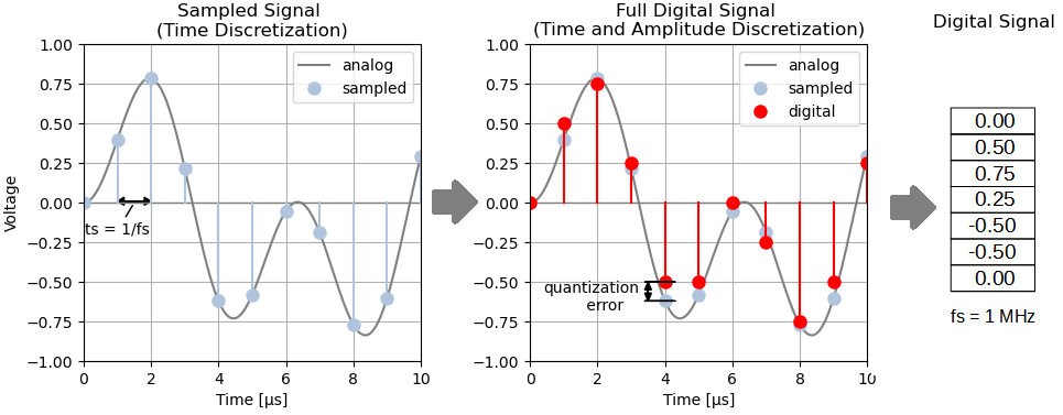
Every SDR receiver uses at some stage an analog-to-digital converter (A/D converter or ADC), that transforms an analog signal to a digital signal. To do so, the AD converter samples the analog signal at regular time intervals and outputs the signal amplitudes as a stream of digital numbers. Essentially, the analog-to-digital converter performs two main steps on the analog signal:
- Sampling, i.e discretization of time
- Quantization, i.e. discretization of amplitude
Discretization of time means, that the ADC measures the analog signal amplitude in fixed time steps of t_s seconds only. Then the sampling frequency equals f_{s} = 1/t_{s}. If e.g. the sampling frequency is 1 MHz, the ADC captures digital samples in time steps of 1 µs (= 1/1 MHz).
Quantization originates from the fact, that digital numbers are represented by bits. A digital number can take only a finite number of values, defined by the number of bits. E.g. an AD converter with 8 bits can output only 2^{8} different values. Quantization can be seen as a “rounding” operation of the analog amplitude in order to obtain a digital value. This “rounding” usually introduces some quantization errors in amplitude. The quantization errors lead to an increase in the noise floor on the digital side (see this excellent tutorial from analog devices). In general, the more bits an ADC converter has, the less quantization noise occurs after AD conversion.
The Sampling Theorem
The Ambiguity Problem
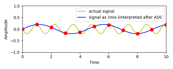
When using sampling to convert an analog signal to a digital one, an important issue arises: Since the digital signal contains only the values at specific sampling points in time, the digital signal is highly ambiguous. To clarify this problem, consider the following digital signal and try to figure out, which analog signal it can actually represent.
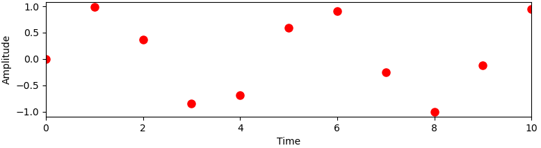
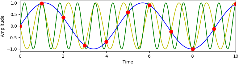
Actually this digital signal can represent many different signals. As an example, the figure below shows three possible signals. But there are many more ambiguous signals, even with non-sine shape, that could fit the digital points.
For digital signal processing, however, it is required to have a clear 1:1 correspondence between the (real-world) analog signal and its digital representation. So a requirement of reasonable analog-to-digital conversion is to resolve the amgibuities in order to establish a clear connection between analog and digital signals.
Nyquist Zones
It is noticable, that the different ambiguous signals in the example above have very different frequencies, which leads to the way to resolve the ambiguity problem: First, we switch to the frequency domain. Next, the frequency spectrum is partitioned in different bands, called the Nyquist zones. Each Nyquist zone covers a bandwidth of 0.5 f_{s} .
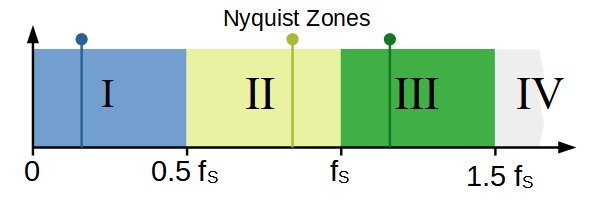
Ambiguous analog signals for a given digital signal occur only between different Nyquist zones. The figure above shows the three ambiguous signals (blue, yellow, green) from the example – they are all located in different zones. If one allows to considers only one Nyquist zone, no ambiguity can occur and the AD conversion is said to be aliasing-free. This is an extremely important goal of analog-to-digital conversion and is summarized in the sampling theorem.
The general form of the sampling theorem gives a rule how to restrict the analog frequency range in order to avoid the ambiguity problem:
Ambiguous signal representations can be avoided, if one considers signals from only one Nyquist zone for AD conversion.
Anti-Aliasing Filters
To avoid ambiguities and aliasing we need to make sure to consider only one Nyquist zone for AD conversion. In practice this is accomplished by rejecting all possible ambiguous signals before analog-to-digital conversion. To ensure this, we place an analog filter before the AD converter, that removes all but one Nyquist zone. This filter is called anti-aliasing filter.
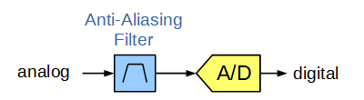
By placing the anti-aliasing filter in front of the ADC, the designer needs to select a Nyquist zone or the band of interest in advance (during circuit design).
The Basic Sampling Theorem
Often AD conversion systems use the first Nyquist zone. In this case the anti-aliasing filter is a low-pass filter with cut-off frequency at around 0.5 f_{s}. The filter ensures, that all analog signals for AD conversion are in the first zone below 0.5 f_{s}.
The typically cited (basic) sampling theorem in literature assumes the use of the first Nyquist zone. It formulates a rule how to select the sampling frequency:
The sampling frequency f_{s} must be higher than twice the highest frequency in the analog signal f_{analog} .
f_{s} \geq 2 f_{analog}
In the following example, an anti-aliasing filter rejcets all but the first Nyquist zone and so establishes a unambiguous 1:1 correspondence between the analog and the digital signal. For the digital signal shown above, only one (real-world) analog signal fit the digital values: the blue one. There is even no other signal shape, that can be fit to the digital points and at the same time contains only frequencies from the first zone.


However, there is no need to stick to the first zone. It is also possible to select another Nyquist zone for AD conversion. This leads to the concept of undersampling.
Undersampling (band-pass sampling)
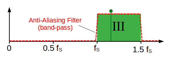
In undersampling (also called band-pass or IF sampling) a Nyquist zone above the first one is selected for AD converison. In that case, the anti-aliasing filter is not a low-pass filter, but a band-pass filter. This band-pass filter rejects all other Nyquist zones and therefore leads to an unambiguous digital signal.

Band-pass sampling is a method to convert fast analog signals with a slow sampling ADC. This is especially interesting, because fast ADCs are expensive, power consuming and create high digital data rates at their output.
What happens if the sampling theorem is violated?
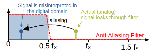
In practice cases may occur, when the designer selects one Nyquist zone for AD conversion, but for some reason frequencies of other zones leak into the ADC’s analog input. This may e.g. happen, if a strong analog signal is not fully suppressed by the anti-aliasing filtering (which may happen near the slopes of the anti-aliasing filter). For these signals the sampling theorem is then violated.
In a practical system, these spurious signals from unwanted Nyquist zones, appear as ghost signals after AD conversion, because the signal is assumed to originate from the originally selected Nyquist zone. This leads to a misinterpretation of frequency on the digital side and consequently it looks as if the signal appears at a different frequency. This problem is often called aliasing.
The example below shows the situation where the designer has chosen the first Nyquist zone for AD conversion. The strong yellow signal from the second Nyquist zone leaks though the anti-aliasing filter. It creates a digital signal, which corresponds to the a different signal in the first Nyquist zone. This is the blue signal, having a much lower frequency and appears as a ghost, because the blue signal is actually not present.
If the first Nyquist zone is selected (basic sampling theorem) the following formular provides the aliasing frequency of the ghost dependent on the analog input frequency and the sampling frequency:
f_{digital}=|nf_s-f_{analog}|
where n is an integer to be chosen such that f<f_{s}/2
Choice of the Sampling Frequency
The choice of the sampling frequency f_{s} sets the borders for the Nyquist zones in the spectrum. A large f_{s} creates wide Nyquist zones and allows to convert a large portion of the spectrum at once. On the other hand, the sampling frequency is limited by the ADC chip and the maximum data rate the digital system can process.
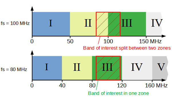
Sometimes it may be required to receive a portion of the spectrum, that spans over more than one Nyquist zone (e.g. if the signal frequencies lie around multiples of f_{s}/2). In these cases, it may be advantageous to change the sampling frequency, such that the band of interest falls into a single Nyquist zone.
The example below shows an analog-to-digital system, that is to receive the FM radio broadcast band at around 85-110 MHz. The first AD setting has a sampling frequency of 100 MHz. The FM band falls between Nyquist zone 2 and 3 and proper AD conversion is not possible. However, lowering the sampling frequency from 100 to 80 MHz changes the arragement of Nyquist zones in the spectrum. Now the FM band falls completely in zone 3 and proper AD conversion becomes possible.
The Influence of Clock Jitter on SNR
A sometimes overlooked property is the quality of the clock source, that generates the sampling clock for the analog-to-digital converter. Every clock generator has tiny but fast random variations in it’s frequency, called jitter or phase noise (for the relationship between jitter and phase noise consider this excellent tutorial from analog devices). Sampling clock jitter introduces additional noise, because due to the jitter the analog signal is (randomly) sampled slightly too early or too late. This results in a small random amplitude error, as depicted in the image below.

Similar to the quantization error, this amplitude error also introduces noise on the digital side, which may lower the overall SNR. The following formula describes the theoretically maximum SNR in dB, that can be achieved for a given clock jitter t_{jitter} (for an otherwise ideal AD converter).
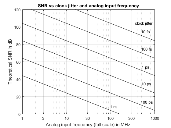
SNR = 20 \,log \left( \frac{1}{2 \pi f_{analog} t_{jitter} } \right)The amount of noise introduced by jitter is not only dependent on the clock jitter itself, but also on the frequency f_{analog} of the analog signal. Fast analog signals are more susceptible to clock jitter noise. This is because fast waveforms change more rapidly and therefore even a small deviation in the sampling time leads to large amplitude error. Note, that the clock jitter noise does not depend on the sampling frequency f_{s}.
The chart below helps determining the clock jitter requirements for a given SNR and the frequency of an analog input signal and is independent of the ADC type. For a setting of shortwave reception up to 30 MHz and an ADC with a nominal SNR of 75 dB, the clock source needs to have a jitter of at most 1 ps. Otherwise the clock jitter degrades the nominal ADC SNR.
Digital Data Rates
The analog-to-digital converter outputs a stream of digital values. These digital values need to be processed by the subsequent digital signal processing system, which is either hardware hardware (processor or FPGA) or software. The data rates at the ADC output directly depend on the sampling frequency of the AD converter. And the sampling frequency is directly related to the analog signal bandwidth: A fast ADC is able to process a high signal bandwidth, but also requires a powerful digital system to handle the high rate of digtial samples. A slow ADC has slower data rates and thus has much less requirements on the digital processing system, but can capture only a small analog bandwidth at the same time.
For SDR this means: There is a strong relationship between instantaneous SDR bandwidth and the digital data rates to process. High SDR bandwidths pose a challenge not only to analog electronics and analog-to-digital conversion, but also to the following digital signal processing hardware and software.


