The AD converter is the heart of every direct sampling receiver. Its properties are crucial for the overall receiver performance. This is because once the signal has been digitized, virtually any receiver performance can be obtained by digital signal processing in FPGA or software. Important ADC figures are SNR, SFDR (spur free dynamic range), analog bandwidth and full scale voltage. It should be noted, that the sole number of bits is of minor importance, because usually some of the least reliable bits carry only noise. The figure ENOB (effective number of bits) considers this issue and describes the number of bits, that are “noise-free”.
The Panoradio relies on the AD9467-250 from Analog Devices, which is a state-of-the-art 16 bit, 250 Msps AD converter with excellent properties:
- SNR: 76 dBFS / 12.3 ENOB
- SFDR: 100 dBFS
- analog bandwidth: 0-900 MHz
- full scale voltage: 2.5 Vpp
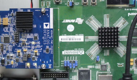
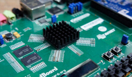
The Panoradio uses the AD evaluation board with FMC connector, that can be easily attached to the Zedboard signal processing platform. The board is equipped with a optional clock generator, a preamplifier (not used) and a clock conditioner (not used) for external clocks. The on-board clock generator (Vectron VCC 6) is of very good jitter performance and therefore used as a clock source here. Some modifications were made on the eval board to enable the clock source and route the signals correctly to the AD converter chip.
Analog AD Converter Frontend
The AD converter AD9467 has differential input signals with an equivalent input impedance of 530 Ohms and 3.5 pF capacitance. Although it is possible to feed single ended signals to the AD9467 it will decrease SFDR performance, so differential signaling is recommended. The purpose of the analog ADC frontend is to convert RF signals from the antenna to differential signals and provide a proper impedance matching from 530 Ohms || 3.5 pF to 50 Ohms at the SMA input jack. The analog ADC frontend is part of the evaluation board. Since the board allows for very different configuration, the design implemented for the Panoradio is shown below.
R5, C6 and R6 form a filter to reduce high frequency noise. R3 and R4 reduce kick-back currents from the ADC sampling process. R1 and R2 are the main parts for the resistive impedance matching, L1 finalizes impedance matching to real 50 Ohms. The transformers convert the single ended signal to differential signals. The reason for using two transformers is because a two transformer configuration reduces the second order distortion in comparison to a single transformer. This is because of parasitic phase and magnitude imbalances in non-ideal (real world) transformers. Especially phase imbalance causes second order harmonics. Since the imbalances quickly rise with increasing frequencies, this becomes an issue for higher speed analog signals (e.g. >100 MHz). A two-transformer configuration reduces the second order harmonics resulting in an improved SFDR for higher frequency signals. See AD’s Wideband A/D Converter Front-End Design Considerations for more information.
Full Scale Analysis
The full scale of the AD converter is given by 2.5 Vpp for the 530 Ohms input. In general the signal power of a sinus waveform is
P = \frac{ U_{pp}^2 } { 8R }with the peak-to-peak voltage U_{pp} = 2.5V the full scale power P_{FS} at the AD input is
P_{FS} = \frac{ ({2.5 \,V}) ^2 } { 8 \cdot 530 \, \Omega } = 1.5 \,mWand in dBm
P_{FS} = 10 \,log_{10} \left(\frac{1.5 \,mW}{1 \,mW} \right) = 1.7 \,dBm.With the SNR of 76 dB and the thermal noise for 125 MHz bandwidth of -93 dBm the ADC’s noise figure is around 19 dB.
However, the situation is different looking at the inputs of the complete circuit with the analog ADC frontend and impedance matching in between. The impedance matching circuit on the board uses mainly resistive matching. Resistive matching has the advantage of being independent of frequency. Thus the match stretches over a large frequency band up to many 100 MHz. However, resistive matches are not lossless as LC matching networks mostly are. The loss introduced by the AD matching circuit is approximately 9 dB, so the full scale power of the complete circuit is approximately
P_{FS} \approx 11 \,dBm.It should be noted that also the noise figure of the ADC is worsened by another 9 dB and sensitivity decreases to a final noise figure of approximately 28 dB.
A Comment on Preamps and Transformers
The full scale power of the AD converter circuitry of +11 dBm is quite large for the application of a direct sampling SDR. A preamp or a transformer may be considered to raise the input level in order to get improved practical dynamic range. The Panoradio uses neither of them for several reasons:
- Large Bandwidth: Since the Panoradio supports sampling the complete spectrum from 0 to 100 MHz including medium wave, short wave and VHF radio, very high signal levels may occur at the antenna output. So overloading of the ADC has to be avoided at all cost. If the full scale voltage is exceeded, massive distortions occur, that block the receiver completely.
- Linearity: Using an active preamplifier always introduces additional non-linear behaviour resulting in increased distortion. Many very good preamps can be found on the market today and indeed many SDRs provide preamplification. The problem of non-linear distortion increases with the number of signals a system processes at the same time. This is problematic for a wideband SDR with large reception bandwidth. Using no preamp immediately excludes possible distortions.
- Transformer: Transformers offer a nice possibility to amplify signals noiselessly. Voltage amplification can be calculated from its turns ratio: N2/N1. The problem with transformers is, that they have parasitic impedances, which limits their use for higher frequencies. At higher frequencies insertion loss increases as well as the imbalance between differential lines, which introduces additional distortion (see above). This effect gets worse for larger turns ratios, i.e. higher voltage gain. For 1:1 transformers (with no gain) this problem can be handled by the two transformer configuration. For larger turns ratios like 1:4 (+6 dB) or 1:9 (+9.5 dB) the maximum usable signal frequency is limited, which heavily impairs performance at 70cm. More information at Analog Devices here and here.
The Clock Jitter Issue for AD Conversion
It is important to consider the clock jitter of the sampling clock, because it may degrade the SNR of the AD converter. More information on clock jitter and SNR: Basics of AD conversion
Clock Jitter and SNR for HF and VHF
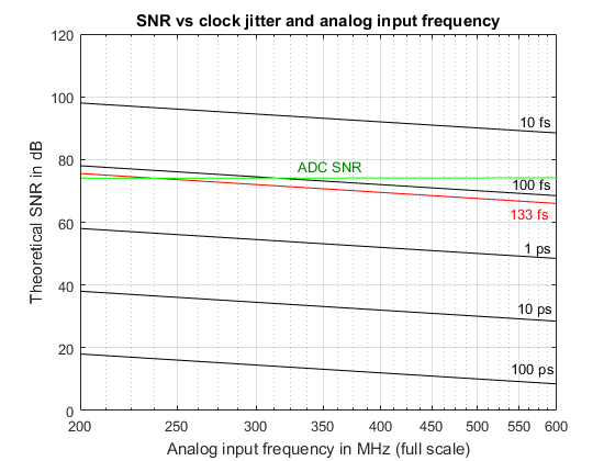
The Vectron VCC 6 clock generator on the AD9467 eval board has a jitter of 133 fs. The figure below shows the theoretical achievable SNR under different clock jitter values. For input frequencies from 0-100 MHz (the Panoradio’s frequency range) the theoretical SNR is always more than 80 dB, which is clearly above the AD Converter’s SNR of 76 dB. So the clock jitter does not affect the noise performance of the receiver.
Clock Jitter and SNR for UHF
Clock jitter is a major issue for direct sampling high frequencies, which should not be taken lightly, because severe degradations in SNR may occur. When using the Panoradio as a direct sampling receiver for 70 cm signals (430 MHz), the impact of clock jitter not negligible. The following figure shows, that for signal frequencies above 240 MHz, SNR is affected by clock jitter. For the 70 cm band the overall SNR is approximately reduced by 7 dB. Therefore the 70 cm front end uses an amplifier to make up for this additional loss. It reduces the overall NF for the 70 cm band from 34 dB to 13 dB.


