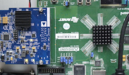
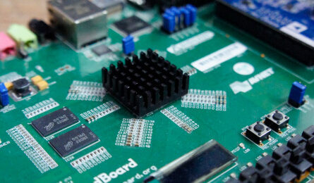
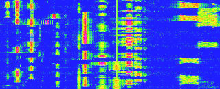
The analog frontend of the Panoradio prepares the analog signal from the antenna for analog-to-digital conversion. This includes filtering and amplification.
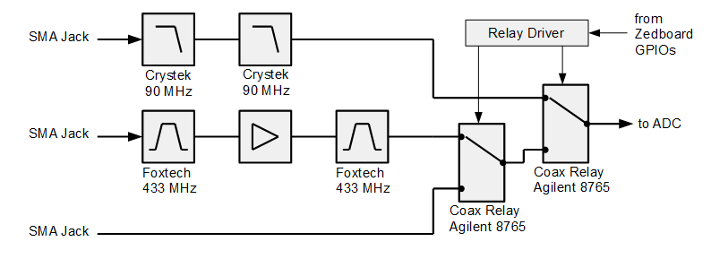
The Panoradio offers three analog input paths and analog frontends for different frequency ranges:
- a 90 MHz low-pass filter (for full panorama view of HF and VHF)
- a direct path without filtering (for experiments and flexibility)
- a 430-440 MHz band-pass filter with an amplifier (for 70cm direct sampling reception)
Anti-Aliasing Filter
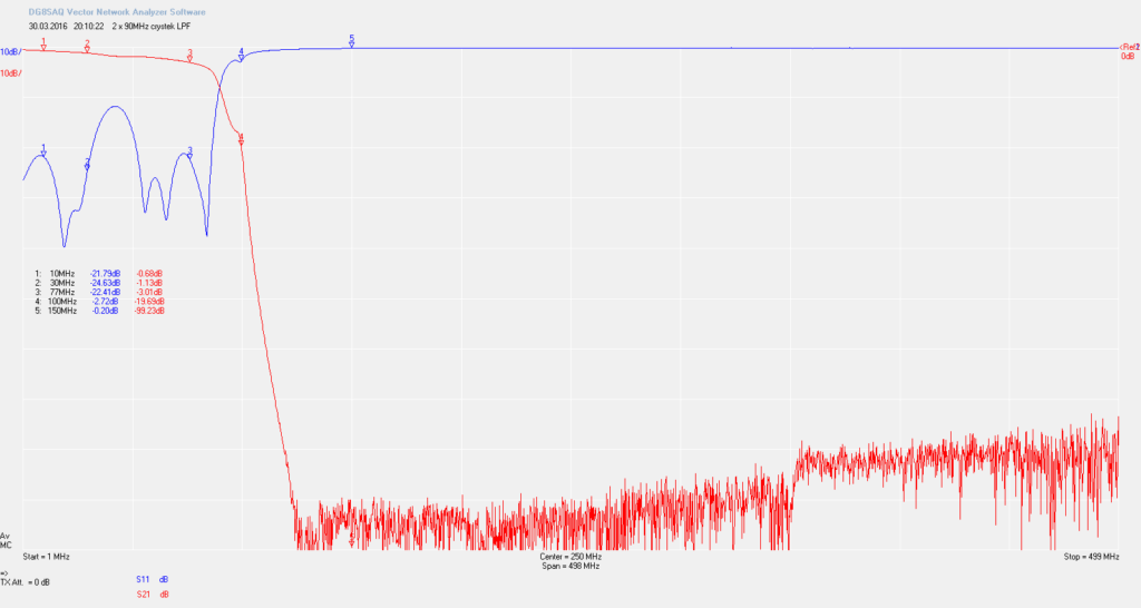
AD converters in a direct sampling receiver require some analog frontend to cope with potential violations of Shannon’s sampling theorem: All analog signals applied to the ADC must have a frequency lower than half the sampling rate, otherwise they will alias into the band between 0 and fs/2. To fulfill the sampling theorem an analog low-pass filter is put before the AD converter, that suppresses all analog signal components above fs/2. This filter is called anti-aliasing filter. It is crucial to achieve high stop band attenuation, because otherwise strong signals from TV transmitters or mobile phone services will interfere with signals originating from 0 to fs/2. Since most analog filters have a quite smooth transition from passband to stopband, the edge frequency of an anti-aliasing filter is usually significantly less than fs/2. SDR builders, who claim a 80 MHz bandwidth with a 160 MHz AD converter, do not properly address the aliasing problem.
In the Panoradio, two 90 MHz low-pass filters consisting of two cascaded Crystek CPFL 0090 filters are used. These filters provide around 55 dB stop band attenuation each, i.e. 110 dB in total. With this high suppression spurious-free dynamic range (SFDR) is not impaired by any aliasing signals, since they are completely eliminated before reaching the AD converter.
Undersampling of the 70 cm Band
Direct sampling SDRs can also receive frequencies above fs/2 with undersampling or bandpass sampling (see Basics on AD conversion). Then the sampling theorem is violated, such that aliasing occurs intentionally. In this case an appropriate band-pass filter is required before AD conversion, that suppresses signals outside the desired band, such that the desired aliasing frequencies do not interfere with out of band signals. The Panoradio uses this technique for direct sampling reception of 70 cm signals.
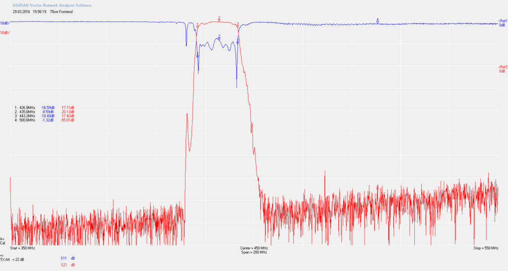
The task of the 70 cm front end is twofold. First it provides suppression of signals out of the 70 cm band (reduces ADC’s NF for 430 MHz from 34 to 13 dB). Second, it amplifies the input signal in order to improve sensitivity. The frontend consists of a 433 MHz band-pass filter (Foxtech BPF 433) with 50 dB stop-band attenuation, followed by a low noise amplifier LNA4ALL (+23 dB, IP3: 34 dBm, NF 1 dB) and a second band-pass filter. The first filter prevents the LNA from overloading by unwanted out-of-band signals. The second filter sets the ultimate anti-aliasing and suppresses broad band noise from the LNA to reach the ADC converter, achieving a total amplification of +20 dB and > 80 dB stopband attenuation.
RF Path Switching
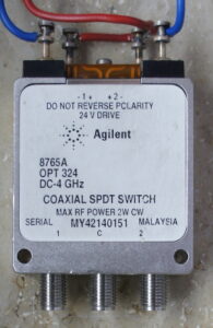
Two high quality bistatic coaxial relays (Agilent 8765A) switch between the three paths. The relays are specified for 24 volts for switching, but they also work with 12 V. Since the Zedboard GPIOs provide 3.3 V the relays are driven with a simple transistor circuit (BC639).

