Digital Down Converter
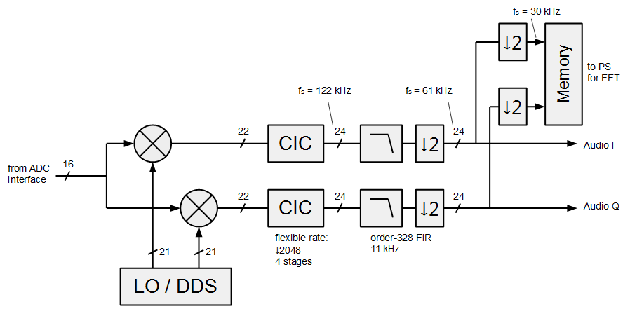
The audio digital down converter (DDC) follows the basic principle of the Panoradio’s waterfall DDC with the exception, that the CIC has a fixed decimation rate of 2048. The FIR filter reduces the bandwidth to 11 kHz, i.e., the total bandwidth for I/Q is 22kHz, which fits well to a 48 kHz sound card. The audio I and Q outputs are passed to the audio postprocessing block for further bandwidth reduction and SSB demodulation, if required. In addition a memory is included to capture samples for a 256 point FFT for the audio receiver waterfall displays. The additional decimation by 2 before FFT memory storage reduces the sample rate and increases FFT resolution. This decimation is not applied to the I/Q outputs, in order not to violate the sampling theorem at the subsequent SSB demodulator output.
The audio digital down converter is designed for high performance: the attenuation of the DDC filters is well below 80 dB, which provides very good attenuation of unwanted signals for practical operation. The filter response for CIC + FIR is shown in the figure below. It compares double precision FIR coefficients and the chosen fixed-point quantization of 18 bits and shows that there is only negligible loss due to coefficient quantization.

The Panoradio features two of the above described audio digital down converters. The I/Q output of the two DDCs are either multiplexed or summed. Summing allows for audio reception of two different bands simultaneously, e.g. to receive and demodulate the PSK31 signals from two bands at the same time.
Audio Postprocessing and SSB Weaver Demodulation
The IQ samples from the audio DDC are fed to the audio postprocessing for volume setting, bandwidth reduction SSB demodulation and sample rate conversion as shown in the figure below.

The first step is a clock domain crossing reducing the FPGA clock frequency from 250 MHz to 100 MHz, which greatly relaxes timing constraints for FPGA synthesis and place & route. This reduction is possible because the signal bandwidth at this point is only several 10 kHz wide and the sampling rate is only 61 kHz.
The clock domain crossing is followed by a software controlled variable gain amplifier for audio volume setting. Additional optional FIR filters can reduce the ultimate audio bandwidth from 22 kHz to 6 or 2.4 kHz. The signals can then be passed as I/Q values directly to the sound card for demodulation or for binaural reception (I and Q mapped to the left and right stereo channel).
For optional SSB demodulation, a Weaver demodulator (also called the “third method”) has been implemented. I consider the Weaver as one of the best options for SSB demodulation in DSP, since the required components, mixers, oscillators and low-pass filters are of low complexity and can be implemented with virtually perfect phase and amplitude balancing. More information on SSB demodulators.
The sample rate after filtering (or optional SSB demodulation) is 30 kHz or 60 kHz depending on the selected filters. In any case this does not match with the 48 kHz sample rate of the Zedboard audio codec. Therefore an additional asynchronous sample rate converter interpolates the input signal at 30 or 60 kHz and filters the output to retrieve the signal at the desired 48 kHz.
Finally the samples are captured by a memory for FFT processing to display the actual audio output spectrum in the Panoradio software GUI.
