With the advent of digital technology, analog circuits in radio transceivers have been widely replaced by digital signal processing. This is because digital signal processing has overwhelming advantages over analog signal processing. Analog circuits are often limited by the laws of physics, that can hardly be overcome. Digital processing is only limited by circuit complexity – a better performance (sensitivity, dynamic range, spurs, agility etc.) is achieved by more (complex) calculations and larger bit widths. Since semiconductor technology continuously advances according to Moore’s Law, very complex systems can be built today and more sophisticated in the future. Therefore it is comparatively easy to achieve extraordinary performance with digital signals.
Filtering
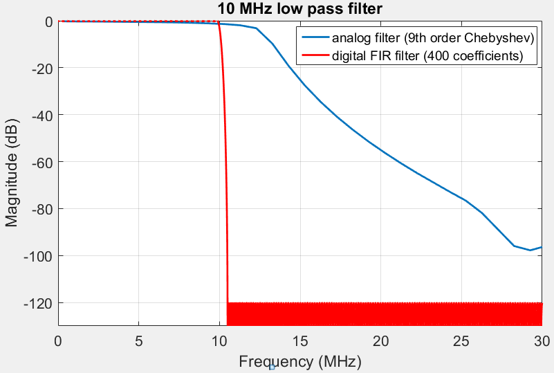
The ideal filter is the well-known brick wall filter with no insertion loss, very steep transition and infinite high stop band attenuation. With analog parts this is hard to achieve because of several reasons: Components like capacitors, inductors, etc. do not exactly match their specified values, have parasitic behaviour (low Q) and suffer from aging. Many components are required to achieve steep transition bands, which is expensive, large and may require sophisticated and cumbersome calibration. Also, low insertion loss is difficult to achieve for filters with many components, as well as very high stop band attenuation.

In contrast, digital FIR filters can be built with virtually any filter response. Low insertion loss, steep transition and high stopband attenuation are only a matter of complexity. In many cases even small sized FPGAs can handle complex filters extremely well. The performance of digital filters can be analyzed very reliably before implementation and do not require extra measurements to obtain the actual filter response.


Mixing
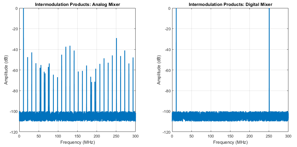
Mixing is the task of multiplying two signals in order to translate the signal up or down in the spectrum. In the analog world, mixers can be implemented in various ways, e.g. as Gilbert cell, switching mixer, diode ring, etc. Analog mixers mostly do not perform the multiplications perfectly, but merely try to emulate a multiplication. This results in many spurs and unwanted intermodulation products.
A digital mixer is simply an arithmetic multiplier, that perfectly multiplies two samples at its input, causing no spurs and no intermodulation at all.

Noise
Noise is omnipresent in the analog world due to physical effects, like thermal noise. Every component in the receiver chain adds a small amount of noise, measured by means of noise figure (NF). Typical values of NF for high performance HF components are roughly spoken in the range of few dBs. In the digital domain noise is not completely eliminated, but the effects are different.
Digital noise is mostly due to quantization, i.e. discretization in amplitude. If one increases the bit width of the digital values, the noise will decrease. By choosing larger bit widths the performance of the radio will improve, however, again at the cost of higher complexity. For the mixer examples shown above, the analog AD831 has a NF of 10-14 dB, whereas the digital multiplier as a NF of 0 dB.
Oscillators
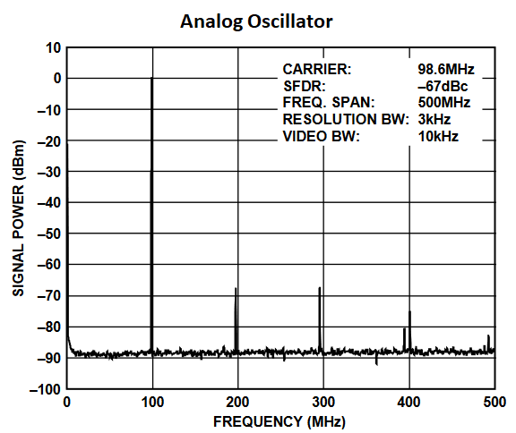
Down conversion by mixing requires a clean oscillator signal, no matter if the signal is analog or digital. Analog oscillators often exhibit harmonics and spurious responses, that have to be attenuated with large effort e.g. with filters. Also switching the frequency in an analog oscillator, such as a PLL requires some time to settle.
Digital oscillators mostly use means of direct digital synthesis (DDS). A DDS basically samples a look-up table containing a fine grained sine waveform. By adjusting the step size of the sampling process for this sine look-up table different frequencies can be generated. Advanced techniques like phase dithering or Taylor series correction at the output provide extremely high spur-free dynamic range (SFDR) with low hardware complexity (e.g. the Xilinx DDS IP core can achieve 150 dB SFDR). Occurring spurs and SFDR can be analyzed very reliably during design time. Furthermore, the frequency of a DDS can change instantaneously without discontinuation in phase.


Amplification
Amplifiers in the analog domain are a science in itself. Care muste be taken to achieve the often required flat response over frequency. Intermodulation, harmonics and other types of distortion (e.g. from the supply voltage) should be as little as possible, which is often hard to achieve in praxis. Moreover, amplifiers with high gain tend to oscillate and require special attention. Typically an amplifier introduces some amount of extra noise, which impairs SNR especially in early receiver stages.
In the digital domain, amplification is just a multiplication, that comes close to an ideal amplifier: There are no non-linearities (resulting in harmonics and intermodulation), no extra introduced noise (noise figure = 0 dB), no gain imperfectness, no bandwidth limitation and no oscillations. A variable gain amplifier is easy to build.
FFT and Band Observation
Digital signal processing offers the possibility to display signals in the frequency domain using FFT. The FFT allows to analyze signals and its frequency components in a large bandwidth simultaneously. Plotting the spectrum over time creates a spectrogram or a waterfall diagram, that is commonly used in SDRs, e.g. for band observation.

Aging, EMC & Impedance Matching
The effects of aging, impedance mismatch and all kinds of EMC issues (grounding, coupling between HF components, noisy power supply etc.), that can bug analog designers so much, are completely eliminated in digital signal processing. Note, that also issues like splitting signals with power dividers are lapsed.
(Re-)Production and Distribution
A sometimes overlooked property of digital radios is that they can be copied easily, since the “design” usually consists of software or other design files, such as programming code, VHDL, FPGA design files or a GNU radio project on a PC. This is a huge advantage for economic industrial production of SDRs. The experimenter and developer can easily create “backups” of the radio or put it under software version control. If modifications made on the radio’s functionality are not satisfactory, the original state can easily be retrieved.


